Building a line following robot using a microcontroller and LEDs
C/C++ Engineering Programming Robotics- August 11, 2023
- August 14, 2023
- Permalink
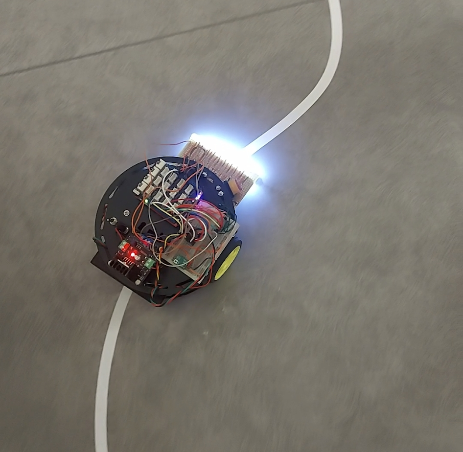
One of the projects in my 3rd engineering year consisted of building a line following robot. The robot had to follow a white line on a grey surface, using the following equipment:
- 1x Arch Pro microcontroller
- 1x turtle chassis
- 2x wheel encoders
- 1x dual motor controller
- 5x photoresistors
- 1x perforated board
- 5x white LEDs
- 2x adjustable infrared distance sensors
- 1x voltage regulator
- 6x 1.2V, 6Ah batteries
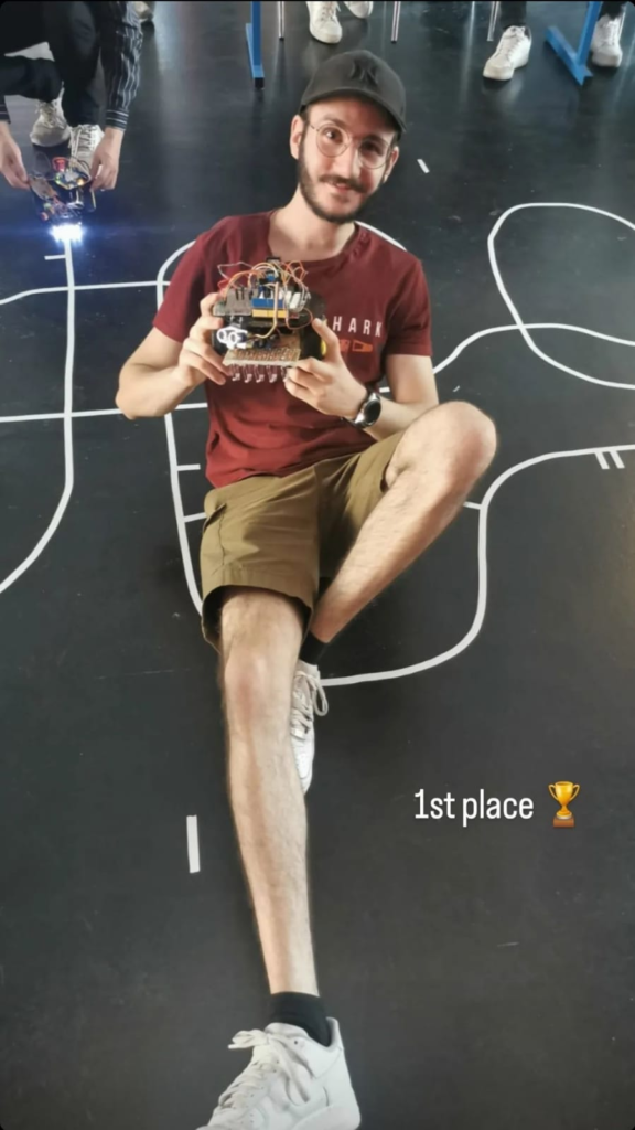
At the end of the project, a competition was hosted where robots competed in a 1v1 to determine which robot was the winner.
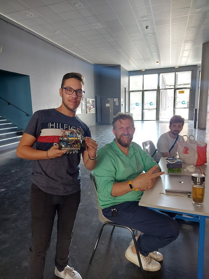
Let’s get to building with my teammate, Lucas Gauvain.
Step 1: The hardware
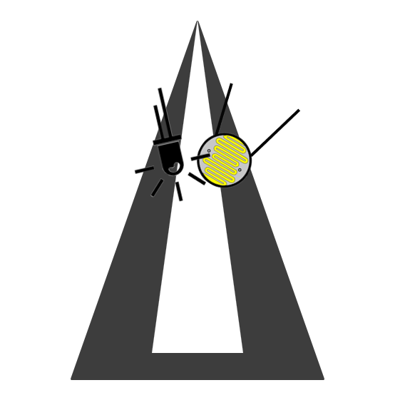
First and foremost, we had to build the robot physically. The most important part of the hardware is the line detection module, which consists of five photoresistor & white LED couples. Our idea was the following: we’ll emit a white light onto the floor and measure the intensity of light reflected off the surface using our photoresistor.
We used basic electronics formulas to determine the values of our resistors to protect the components and limit the voltage going to our microcontroller’s analog-to-digital pin (ADC) at the output of the voltage divider bridge. I’ll spare you the calculation details, but here’s the circuit diagram for each of the couples:
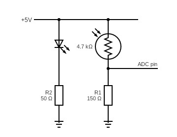
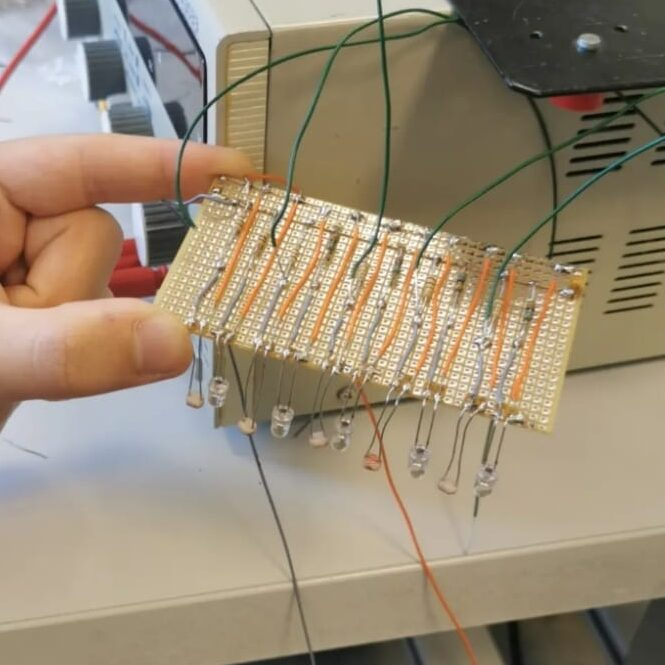
We finally soldered those couples onto the perforated board, and tested each couple on an oscilloscope by sweeping them from a gray surface to a white surface, expecting the voltage to rise as the color goes from dark to light.
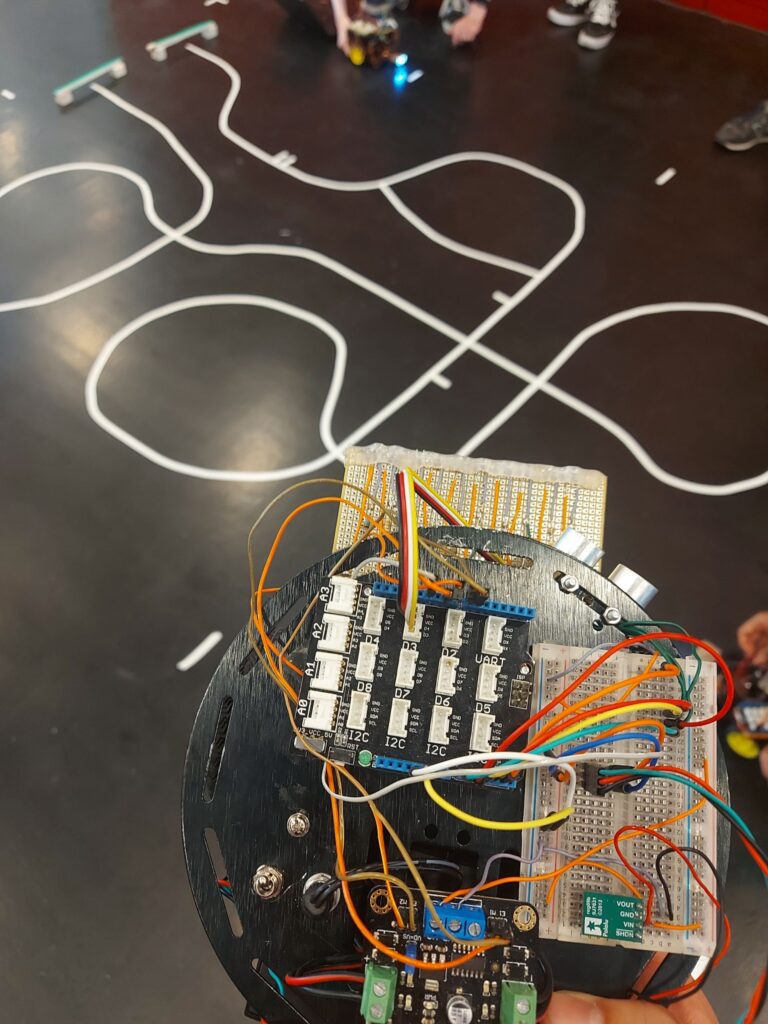
We then assembled the wheels, motors, motor encoders and motor controller on the chassis, and installed the infrared sensors and ultrasonic sensor on the front side of the chassis.
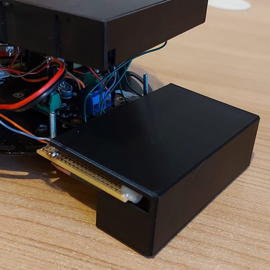
We wanted to be “real” engineers, so we decided to try “innovating” our little masterpiece. We thought that variations in ambient light might interfere with our detection algorithms, so on the hardware-end, we wanted to minimize those variations by 3D-printing a beautiful shield that sits above our LEDs. We made several measures to be millimeter-precise with our 3D model.
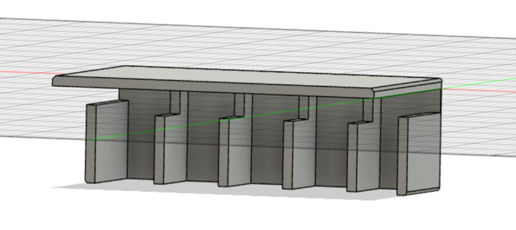
Shoutout to Sorbonne University’s FabLab, where we were able to 3D print our model for free. The resulting 3D object was mind blowing, and perfectly fit our robot.
This will greatly improve our robot’s stability! Or so we thought… In the end, it sometimes improved but other times deteriorated the line following stability, so we ended up removing the shield.
And that’s it for the hardware part! I of course omitted lots of details and bugs for the sake of simplicity.
Step 2: The software
We went with an Object Oriented Programming (OOP) style to clearly separate our logic into multiple classes, so our main.cpp file is surprisingly simple:
#include "mbed.h"
#include "LPC17xx.h"
#include "Driver.cpp"
Driver* driver;
int main() {
    driver = new Driver();
    driver->calibrate();
    wait(1);
    while(1) {
        driver->updateMotors();
    }
}
The Driver class does most of the heavy-lifting as you can see. First we instantiate this class, then we start calibrating our photoresistors.
Each photoresistor has a different range of values it can take due to production errors, so for the same color with the same intensity, the value perceived by each of the photoresistors will be different. To correct for this, we perform a calibration.
The calibration works by measuring the minimum (the grey surface) and the maximum (the white tape) intensity a photoresistor will take. Once we have those values, we can use a new interval which is harmonized between all photoresistors.
class Driver {
    ...
    void calibrate() {
        for (int i = 0; i < 5; i++) {
            white_luminances[i] = 0;
            black_luminances[i] = 1;
        }
        for (int i = 0; i < 4000; i++) {
            for (int j = 0; j < 5; j++) {
                float reading = photoresistors[j]->read();
                white_luminances[j] = MAX(white_luminances[j], reading);
                black_luminances[j] = MIN(black_luminances[j], reading);
            }
            wait_ms(1);
        }
    };
    ...
}
During the calibration process, we obviously move the robot in a such a way that every photoresistor will go from grey to white to grey to white and so on…
Now that we have calibrated our photoresistors, we can accurately detect where on the line our robot is by reading normalized intensity values (“I” being the intensity) using this formula, which will always output a number between 0 and 1, 0 being black and 1 being white:
$$I_{normalized}=\frac{I_{read}-I_{black}}{I_{white}-I_{black}}$$
class Driver {
...
float* readSensorArrayNormalized() {
for (int i = 0; i < 5; i++) {
sensor_array[i] = photoresistors[i]->read();
if (sensor_array[i] > white_luminances[i]) {
sensor_array[i] = 1;
} else if (sensor_array[i] < black_luminances[i]) {
sensor_array[i] = 0;
} else {
sensor_array[i] = (sensor_array[i] - black_luminances[i])/(white_luminances[i] - black_luminances[i]);
}
}
return sensor_array;
}
...
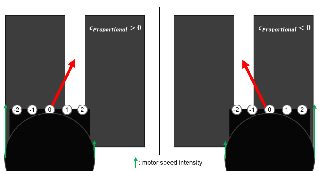
}Now, to detect where the line is and how much to steer, we’re going to use a PD controller (PID without the integral term) to calculate an error, which represents how far off the line our robot is. Here’s how it works. We first assign a weight to each LED:
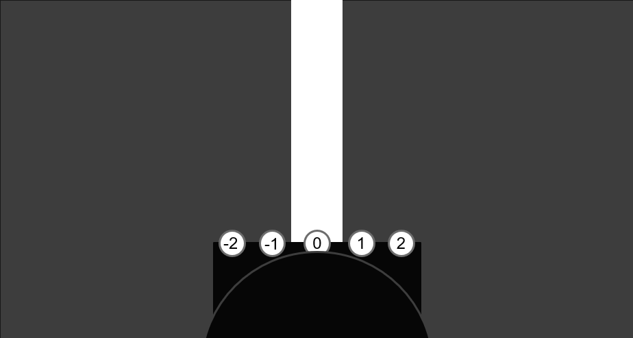
To calculate the proportional error, we take the sum of weighted intensities of each photoresistor, so in our case:
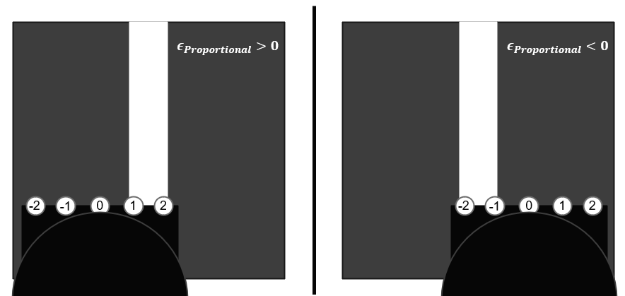
$$\epsilon_{Proportional} = -2 \times I_{-2} – 1 \times I_{-1} + 0 \times I_0 + 1 \times I_1 + 2 \times I_2$$
This gives us an error that can be positive or negative. A negative error indicates that the line is on the left while a positive error indicates that the line is on the right, and obviously a null error indicates that the robot is exactly on the line.
Next, we need to calculate the derivative error, which is simply equal to the subtraction of the current calculated error from the last calculated error.
The final error, then, is the proportional error multiplied by a proportional coefficient, plus the derivative error multiplied by a derivative coefficient. The Kp coefficient is used to correct the error, while the Kd coefficient is used to guide the robot to the white line in a smooth and stable manner. Here is a video demonstrating the effect of each of those coefficients.
$$\epsilon = \epsilon_{Proportional} \times K_p + \epsilon_{Derivative} \times K_d$$
These coefficients should be calculated using trial and error:
- Start by fixing Kd = 0 and Kp = 0.3
- Modify Kp until the robot becomes reasonably stable (corrections don’t happen too slowly or too fast)
- Fix Kd = 0.4 then fine-tune Kp and Kd in small increments until the robot performs smooth corrections
In coding terms, this simply translates to:
class Driver {
    ...
    static bool isOnMainLine(const float* sensor_array) {
        return sensor_array[2] > 0.7;
    }
    static bool isOnLine(float sensor) {
        return sensor > 0.7;
    }
    float getError() {
        float* readings = readSensorArrayNormalized();
        if (isOnMainLine(readings) && isOnLine(readings[0]) && isOnLine(readings[1])) {
            return 0;
        }
        if (isOnMainLine(readings) && isOnLine(readings[3]) && isOnLine(readings[4])) {
            return 0;
        }
        float error = 0;
        for (int i = 0; i < 5; ++i) {
            error += (float)(i-2)*readings[i];
        }
        float P = error;
        float D = error - last_error;
        last_error = error;
        float delta_motor_speed = (P*Kp + D*Kd);
        return delta_motor_speed;
    };
    ...
}
Obviously, we need to ignore intersection markers and intersections themselves since they will interfere with the error calculation process, so if any of the mentioned situations are detected, we simply return a null error.
We can now use the value calculated to instruct the left and right motors to change their respective speeds. Here’s how this works: each motor has a base speed which determines how fast it moves if the error is null. When a disruption is picked up by the PD controller, the motors will adjust their speeds to steer towards the desired position. For example, if the error is negative and the robot is on the right of the line, it will steer towards the left (which means the left motor should be slower than the right motor) and vice-versa. The slower motor can even turn in the opposite direction if the error is too big.
In programming terms, this gives the following:
class Driver {
    ...
    void updateState() {
        // To be done
    }
    void updateMotors() {
        updateState();
        float motor_speed = getError();
        float left_motor = base_speed + motor_speed;
        float right_motor = base_speed - motor_speed;
        if (left_motor >= 0) {
            motor_left_direction->write(1);
            if (left_motor <= 1) {
                motor_left_speed->write(left_motor);
            } else {
                motor_left_speed->write(0);
            }
        } else {
            motor_left_direction->write(0);
            motor_left_speed->write(-left_motor);
        }
        if (right_motor >= 0) {
            motor_right_direction->write(1);
            if (right_motor <= 1) {
                motor_right_speed->write(right_motor);
            } else {
                motor_right_speed->write(0);
            }
        } else {
            motor_right_direction->write(0);
            motor_right_speed->write(-right_motor);
        }
    }
    ...
}
Great! The line following part is done! Please note that I did not include all constants and properties used in the Driver class in the above snippets. It is up to you to add them according to your specific setup.
Step 3: Obstacle detection
Now that we have achieved the hardest part, we can add obstacle detection capabilities to avoid collisions with other robots during the competition.
We originally wanted to use our infrared sensors as well as our ultrasonic sensor. But after some tests, we discovered that the infrared sensors had a very hard time detecting the black chassis of other robots, which constrained us to only using the ultrasonic sensor, which we’ll be using to sense robots coming on our right on intersections. For this, we’ll use a state enum variable to keep track of the various states our robot is in:
typedef enum reading {
    NONE,
    INTERSECTION,
    POST_INTERSECTION
} t_reading;
class Driver {
    ...
    t_reading state; // initialize to NONE in constructor
    void updateState() {
        float *readings = readSensorArrayNormalized();
        if ((state == INTERSECTION || state == POST_INTERSECTION) && distance >= 150) {
            // If we have travelled 15cm from the last intersection, reset the state to NONE
            state = NONE;
            setDistanceMeasurer(false);
            distance = 0;
        } else if (isOnMainLine(readings) && !isOnLine(readings[0]) && !isOnLine(readings[1]) && !isOnLine(readings[3]) &&
            !isOnLine(readings[4])) {
            // Main line: 00100
            // Set the state to POST_INTERSECTION once we're past the intersection marker and reset distance counter
            if (state == INTERSECTION) {
                state = POST_INTERSECTION;
                distance = 0;
            }
        } else if (isOnMainLine(readings) && !isOnLine(readings[0]) && !isOnLine(readings[1]) && isOnLine(readings[3]) &&
            isOnLine(readings[4])) {
            // Intersection: 00111
            // Set the state to INTERSECTION once we encounter the intersection marker (a white tape on the right), and start measuring the distance traveled
            if (state == NONE) {
                state = INTERSECTION;
                setDistanceMeasurer(true);
                distance = 0;
            }
        }
    }
    void setDistanceMeasurer(bool enabled) {
        if (enabled) {
            right_distance->enable_irq();
        } else {
            right_distance->disable_irq();
        }
    }
    void rightDistanceUpdate() {
        distance++;
    }
    ...
}
The way the distance measurer works is by using the wheel encoder and interrupt signals to increment the distance counter every time one of the 10 encoder teeth go in front of the encoder sensor. You can find more information on how this module works here.
Now that we have a function keeping track of the state, we can instruct our robot to stop when we detect an obstacle:
class Driver {
    ...
    void updateMotors() {
        updateState();
        if (state == INTERSECTION || state == POST_INTERSECTION) {
            if (obstacleDetected()) {
                stopMotors();
                wait(4);
                return;
            }
        }
        ... // the rest of the function mentioned earlier
    }
    void stopMotors() {
        motor_left_speed->write(0.0);
        motor_right_speed->write(0.0);
    }
    bool obstacleDetected() {
        // We consider that there is an obstacle when it is closer than 13cm
        return (ultrasonic->read_m()*100) <= 13;
    }
    ...
}
And that’s it! Our robot will now stop once it senses another robot on an intersection. It will wait for at least 4 seconds before trying to move again (if the obstacle is no longer in view, of course).
Closing thoughts
Well that was quite long! I had a lot of fun working on this project with Lucas, and I learned a lot of invaluable skills from soldering to electronics and OOP programming. Special thanks to Yann Douze and Sylvain Viateur who were always here to guide us and help us finish this project successfully. You’re probably wondering if we won the competition. What a silly question… of course we did!
 Christopher Al Khawand
I’m a university student currently living in France, in my 4th engineering year at Sorbonne University.
Passionate about programming, solving complex IT problems as well as new technological progress, learning new skills never stops.